
First things first we should go over what a microcontroller is. At the most basic level a microcontroller is a small computer that can listen for inputs and respond with outputs on its various Input/Output (IO) pins.
Before we begin working with the microcontroller we will need software to write and upload our programs to it. We will be using the Arduino IDE(Integrated Development Environment) for all examples in this guide. The Arduino IDE is easy to use and beginner friendly. Click the link below and follow the steps provided on the arduino site to get the IDE installed and ready to use.
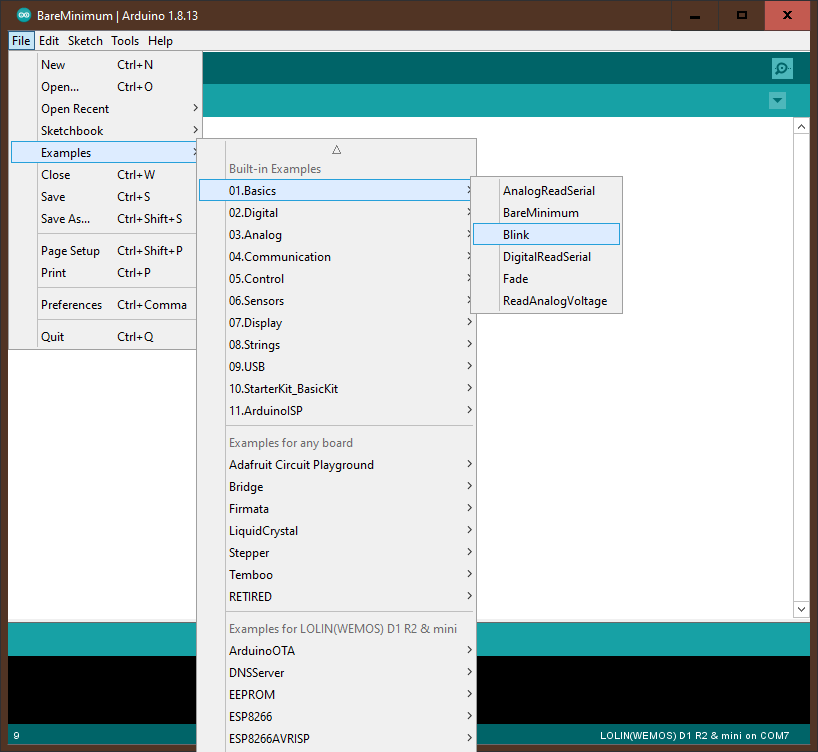
We are going to open an example program to learn some basics. Click on file in the top left and in the dropdown menu find “examples”. Hover over it and then hover over the option labeled “basic” and then in the new menu click on the option labeled “blink”.
After the comments on the program we see a function declaration. This function is called setup and it is special. The setup function is run automatically once as the first thing the Wemos does when it is powered on. The setup function is used to set everything up for the program to work properly. Clear displays, reset variables, etc.
The next thing we see is the loop function declaration. Loop is another special function that runs repeatedly as fast as possible. After setup is done loop will immediately be called and will not stop until the Arduino is unplugged.
Every program must have one and only one setup and loop function in order to work.
The first and only line in setup is a call to the function PinMode with
the parameters LED_BUILTIN and OUTPUT. But wait we didn't define a pinmode
function or the variables LED_BUILTIN or OUTPUT? This function and the
variables used are pre built into the arduino and allow us to interface
with it. LED_BUILTIN is special and will vary depending on the board we
are using. We will see and go over a few more of these as we continue but
if you want to do your own research you can go
here
and see all of the built in functions that can be used. The pinmode
function tells the arduino whether the specified pin should be an input or
output pin. If the pin is input then we are expecting to read from the pin
and we will be sending voltage into it. If the pin is output then we
are expecting to drive the pin and either send voltage from it or not. It
is important to set all the pins we will be using to the mode they will be
used in in the setup function.
In order to use the pinmode function we just need to put in the pin we will
be using as the first parameter and the mode as the second. To get the name
of the pin just look at the top of the Arduino and the white text next to
each pin is the name of the pin to use. If we wanted to set pin D1 to
output and pin D3 to input we would right it like
pinMode(D1,OUTPUT);
pinMode(D3,INPUT);
If we now look at the loop function of our blink sketch we can see the first line is
digitalWrite(LED_BUILTIN,HIGH);
This line means that we are going to drive the LED_BUILTIN pin High which means we are sending voltage out from it.
LED_BUILTIN can be replace with any pin we have setup to be output for example
digitalWrite(D1,HIGH);
The next line we see is
delay(1000);
This is another built in function that will delay the execution of our program for however many milliseconds we put as the parameter. 1 millisecond is 1/1000 of a second so 1000 milliseconds is a one second delay
After these two lines we have basically the same thing again except this time we digitalWrite the builtin pin low which means we turn off the voltage. We delay for another second and then the loop starts again at the top.
Now that we know how to write to our pins the next thing we need to do is learn to read information from them.
When working with electric circuits we have a positive and a negative like the ends of a battery. When we connect + and - with a wire we get electricity flowing from the positive to the negative. On most arduinos we can get + from the pin labeled 3v3 and we can get - from the pin labeled ground. + is also called vcc or positive, - is also called ground or negative
In order to do this we first need to set our pins to be input
pinMode(D1,INPUT_PULLUP);
What is INPUT_PULLUP??
INPUT_PULLUP is a special kind of input that we know will always be high (have voltage flowing to it) unless we connect it to our ground. Imagine we have a teeter totter and when the left side is up the pin is high and when the left side is down the pin is low. Connecting the pin to ground is like pulling down on the left side. We know that when we pull down the value is low but what if we release the teeter totter. The teeter totter will probably go back to somewhere in between high and low. The arduino gets confused in a state like this and sometimes might think it is high and sometimes think it is low. Setting the pin to INPUT_PULLUP is like putting a weight on the right side of the teeter totter. Now if we are not pulling the left side down the weight on the right will always keep the left side high and it will only go low when we pull it.
In order to connect the D1 pin to ground we want to have the
connection between them only active when the button is pressed. To do
this we are going to set up our first circuit on the breadboard.
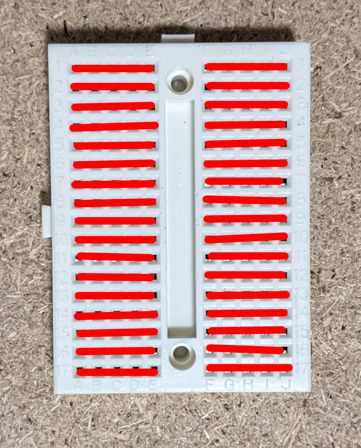
Let's look at the breadboard that comes with the kit. All of the
holes in a row are connected together but each row is separated from
the others. The rows are also separated by the space in the middle so
a row on the right is not connected to the left.
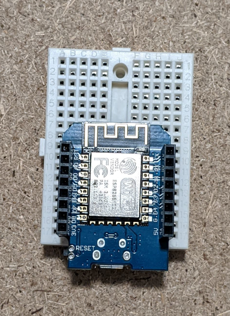
 Step one is to plug our Arduino into the breadboard (We are using a
Wemos D1 Mini in the example). We want the Arduino to be in the middle
so that there is one column of pins on either side. We also want it so
that the pins closest to the micro usb port on it are in the first
holes of the board like so
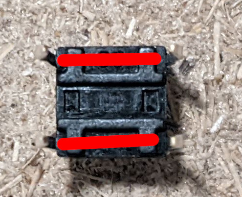
 Take the button included in your kit and look at the bottom of it. You
should see that the bottom is split into three sections. The two legs
on the left side are always connected together and the same with the
two legs on the right but the left and right are only connected when
the button is pressed.
 We want the left and right sides of the button to be on different
rows so that when we press the button the two rows are connected
together.
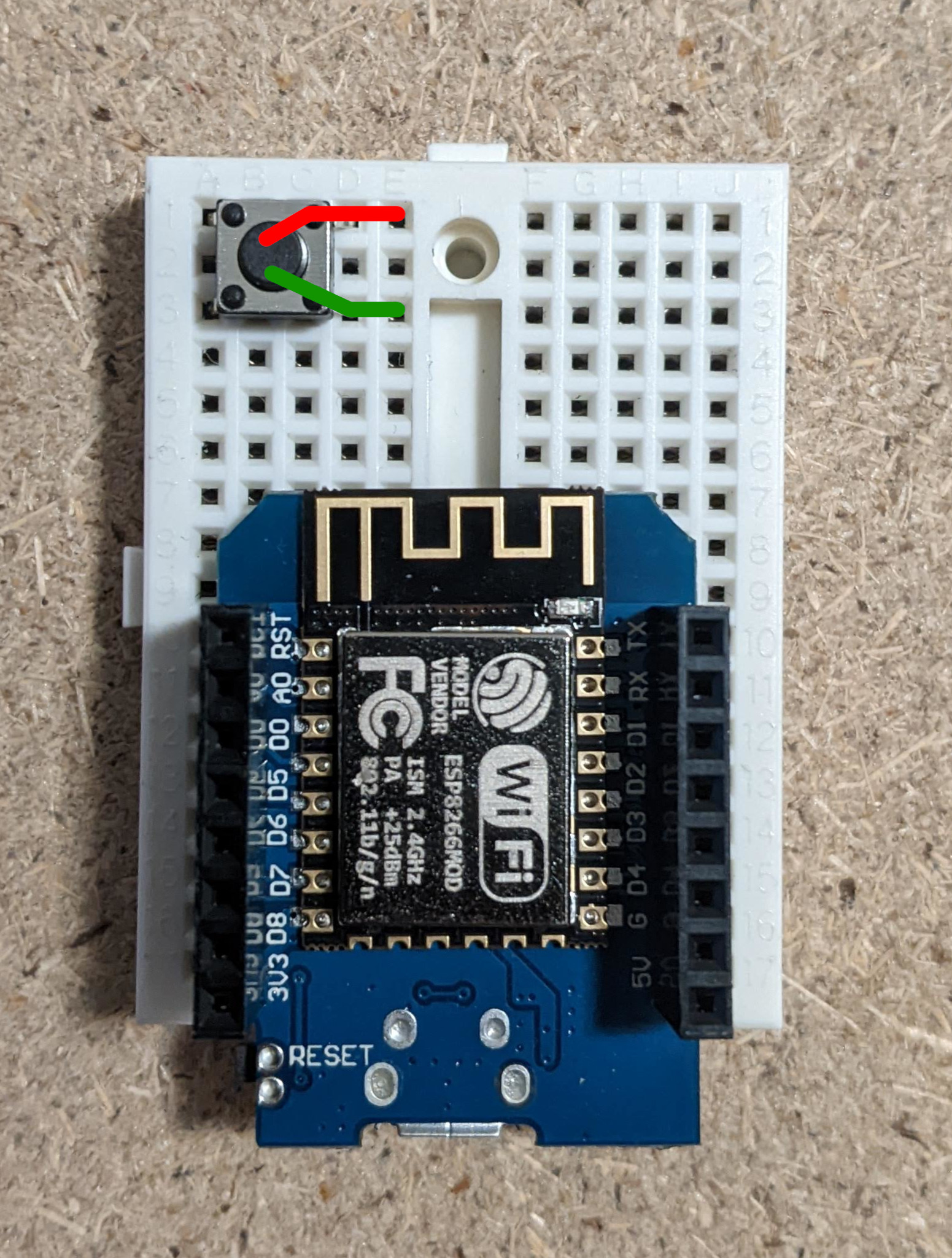 Now we just need two wires. One will connect pin D1 to the one of the
rows the button is connected to and the other wire will connect the
other side to ground.
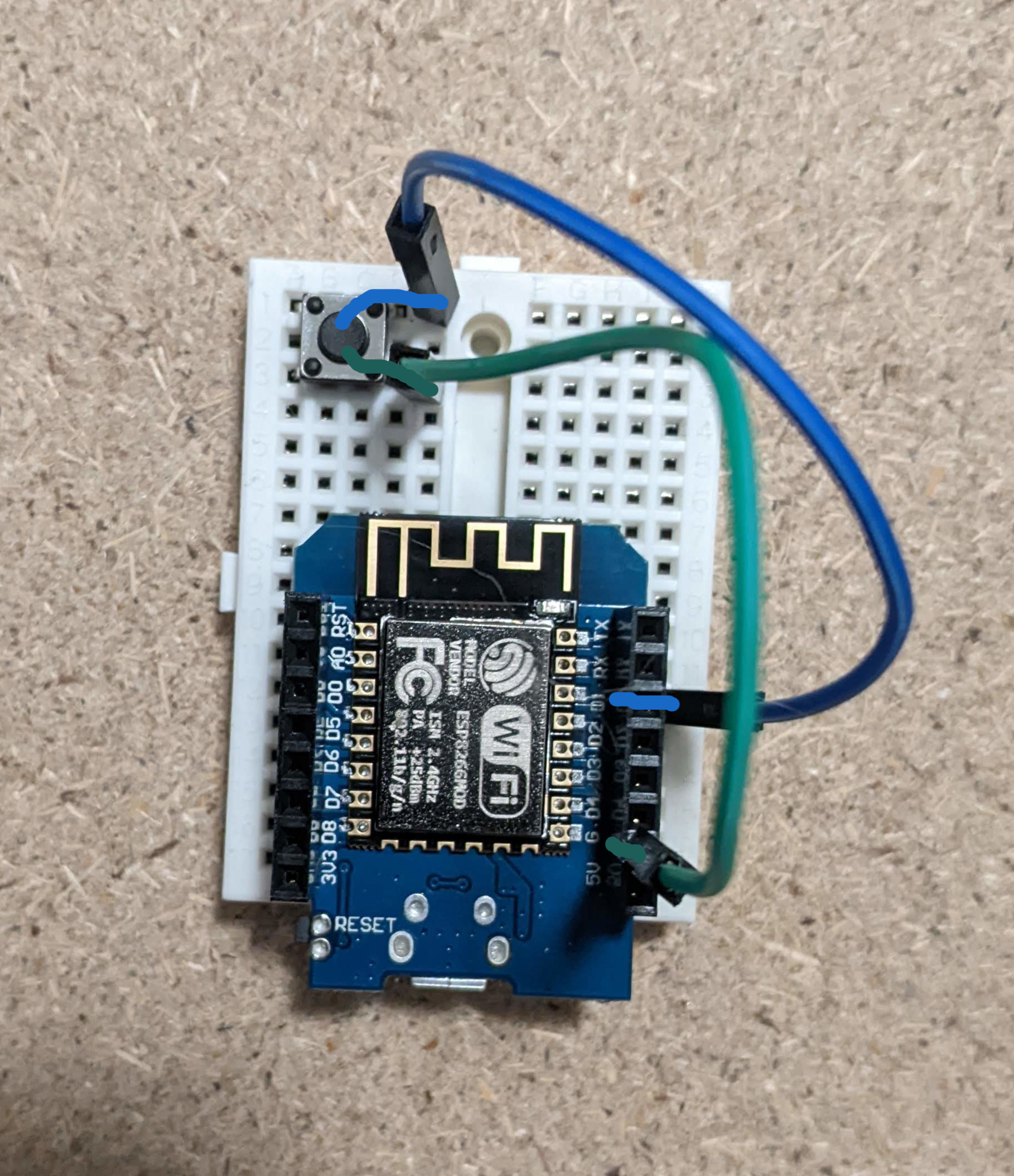 Congratulations you have created your first circuit. In this circuit
when the button is not pressed pin D1 is not connected to ground and
when the button is pressed it gets connected.
Now that we have our circuit setup we can go back to our code. In our setup function we already have
void setup(){
    pinMode(D1,INPUT_PULLUP);
}
But we need a way to see if pressing the button is actually doing something. Lets add our LED_BUILTIN pin as output
void Setup(){
    pinMode(D1,INPUT_PULLUP);
    pinMode(LED_BUILTIN,OUTPUT);
}
Now that we have our pins and circuit set up we can read the value from d1 and set the value of LED_BUILTIN in our loop. First we read the value from D1 and save it to a boolean variable
High is equal to true and low is equal to false
void loop(){
    bool buttonState = digitalRead(D1);
}
We have used another builtin function here called digitalRead. Digital read does just what it sounds like and reads the state of the pin we pass in as a parameter. Remember that we are using INPUT_PULLUP so unless we are pressing the button this value should be high (or true). Now that we know what state our button is in we just need to set our LED_BUILTIN to match it.
void loop(){
    bool buttonState = digitalRead(D1);
    digitalWrite(LED_BUILTIN,buttonState);
}
If we press the upload code arrow in the top left and wait for the program to be uploaded we should see the light turn on, and when we press the button it turns off. Congratulations you have coded your first arduino project.
Change the code so that when we press the button the light turns on and when we release it the light turns off?
You need to use the not operator(!)
So far we have a circuit that will connect pin D1 to ground when a button
is pressed. We are going to add to this circuit so that instead of
lighting up the built in led we will light up a separate led. Take one
led, one resistor, and one more wire out of the box. In order to make the
led light up we need to connect the long leg to + and the short leg to -.
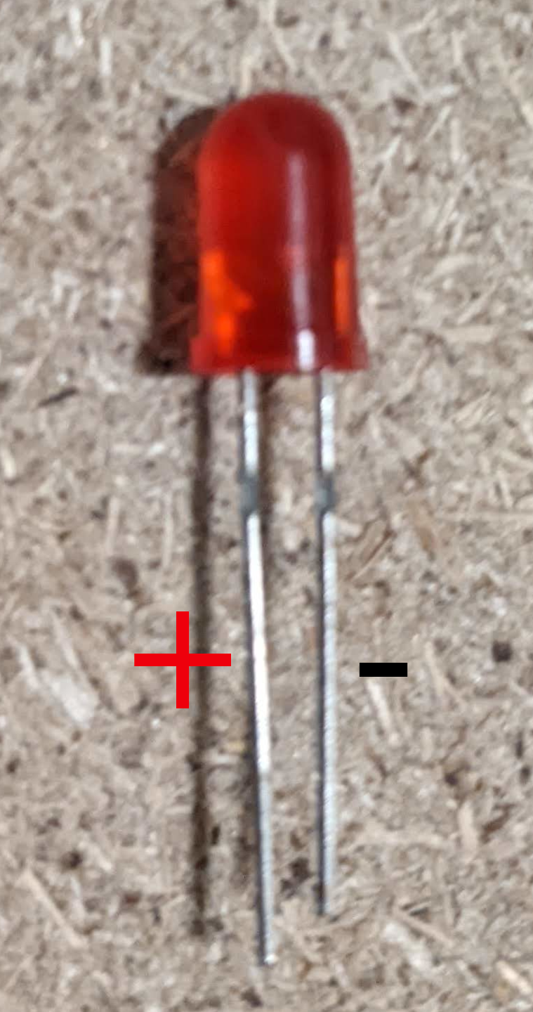 In this case however we don't want to directly connect the short leg to
ground. If we connect the LED directly to power and ground then there will
be too much power flowing through it and it may work for a while but will
eventually overheat and fail. To prevent too much power flowing through it
we connect the short leg of the LED to ground through the resistor. The
resistor slows down the flow of power through the led to keep it safe. Plug
the led in so that the long leg is on one row and the short leg is on
another. Using one of the wires connect the long leg of the led to pin D3
and connect the short leg to ground with the and a wire
resistor like so. The LED may light up at this point and that is okay.
Since we have not defined D3 as an output pin its state is not set and
could be high or low.
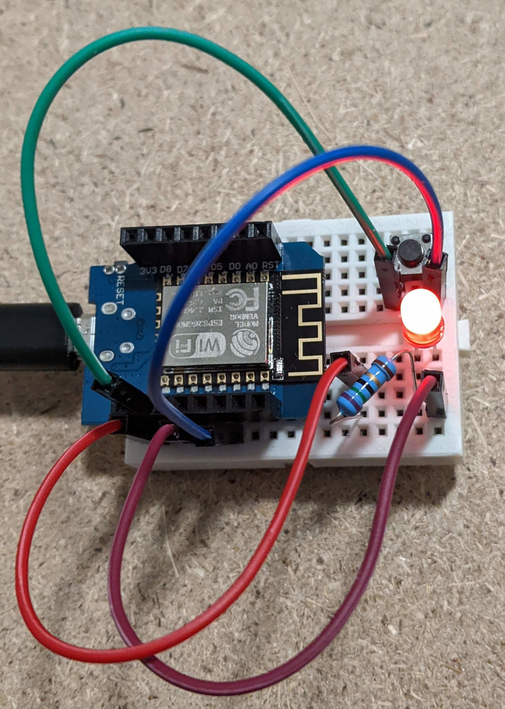 Now that we have this led set up we only need to make one small change to
our program to make it work. Instead of using the LED_BUILTIN pin we will
use pin D3 like so
void setup(){
    pinMode(D1,INPUT_PULLUP);
    pinMode(D3,OUTPUT);
}

void loop(){
    bool buttonState = digitalRead(D1);
    digitalWrite(D3,buttonState);
}
Now when we set D3 to high we will have voltage flow out of it through the led and back to ground which will light up the led. And when we set D3 low we turn off the voltage to that pin and turn off the led. Upload the program and you should see the LED we set up turning on and off when we press the button. Recall that when we use INPUT_PULLUP on D1 we are keeping it high until we connect it to ground, so the default state of the LED is on. The LED_BUILTIN has a circuit on the board so that it inverts the state it is set too. This is somewhat confusing but just remeber that the LED_BUILTIN is a special case and you can normally expect something to be on when set high and off when set low.
Sometime we need more information about what is happening in our program.
We could set up a bunch of lights and decode them to figure out what's
goin on but luckily there is a feature built in to the arduino IDE that
will let us get messages from the arduino in plain english. This feature
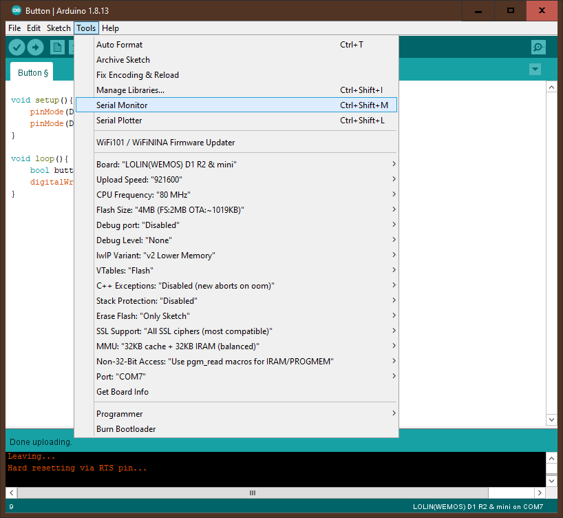
is called the Serial monitor. If you look under the tools menu you will
see an option for the serial monitor. Click on that and a new window will
pop up.
void setup(){
    Serial.begin(115200);
}
The 115200 as a parameter is the speed of the communication between the
computer and the arduino. We need to make sure that in the serial monitor
window the read speed is set the same
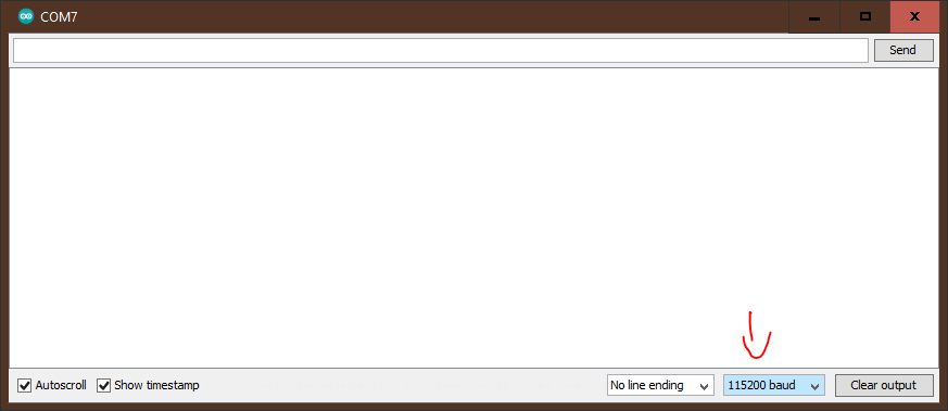
115200 is to fast for some arduinos. If after following the setup the serial output does not work try using 9600 instead
Now that we have begun serial communication we can write whatever we want to the Serial monitor. To do this we just have to type Serial.println() with the message we want to send in the parentheses so for example.
void loop(){
    Serial.println("Serial is working!!");
}
So our finished serial program is
void setup(){
    Serial.begin(115200);
}

void loop(){
    Serial.println("Serial is working!!");
}
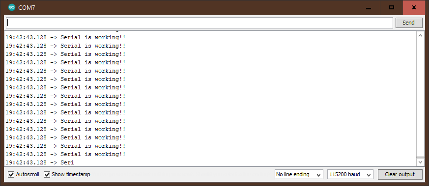
Now if we upload the program and open the serial monitor we should see this
Have the program print your own text every one second
Remember the delay() function
Remember that string needs to have double quotes(“) on both sides
Have the program print something out when the button is pressed
You need to use if statements
When we work with digital read the results are always 1 or 0. 1 for high
and 0 for low. What if we wanted to read something like the position of
our potentiometer. We can do this with analogRead(). For analog read we
need to use the A0 pin (A standing for analog). Some other
microcontrollers will have more than one analog pin but the wemos only
has 1. When we use the analog read function we are basically checking
the voltage that is flowing into a pin. Analog read will return us a
number between 0 for 0 volts all the way up to 1024 for 3.3v. In order to
make our potentiometer work we need to connect its three pins. Put the
potentiometer on the board so that when looking at it from the back the right pin
is in the top left most hole on the breadboard. The pin on the left should
get a wire from its row to the 3v3 pin of the arduino. The
middle pin should get a wire from its row to the A0 pin. The pin on the
right should get a wire from its row to ground.
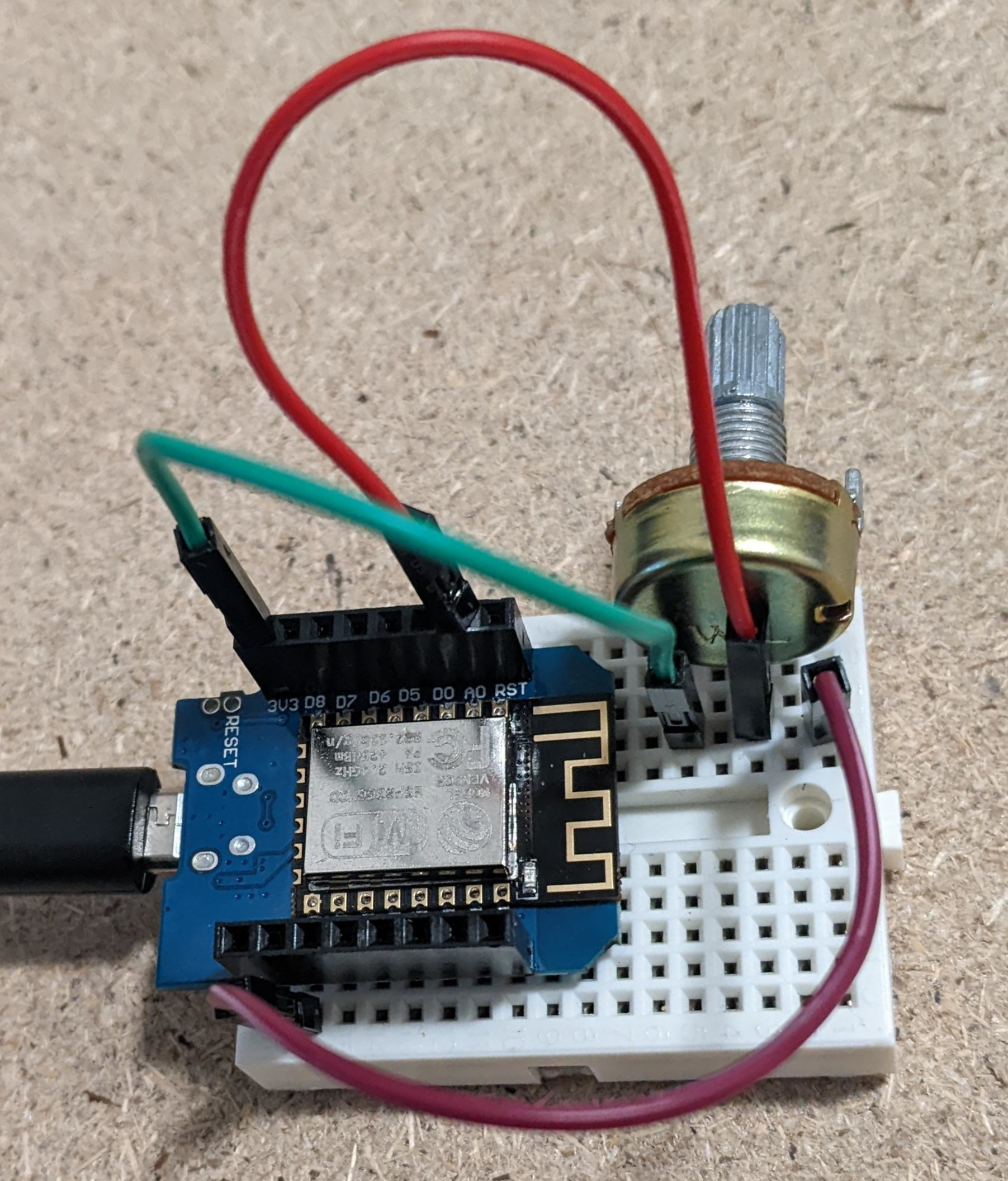 When we turn the
potentiometer you can think of it as connecting the middle pin more to
the side we are turning it towards. So when it is turned all the way one
way it connects a0 directly to 3.3v and when it's turned all the way the
other way it's connected to ground. Let's see if the potentiometer is
working. Start by beginning serial communication in setup
void setup(){
    Serial.begin(115200);
}
Next in loop we want to read the value from the analog pin A0
void loop(){
    int potVal = analogRead(A0);
}
Finally we want to print the value we get to the serial monitor
void loop(){
    int potVal = analogRead(A0);
    Serial.println(potVal);
}
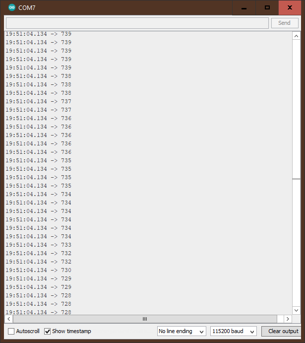
If we upload this program and open the serial monitor you should see the value of the potentiometer being printed out. Try turning the potentiometer and notice how the value fluctuates.
One final thing that we need to touch on are libraries that you can get in
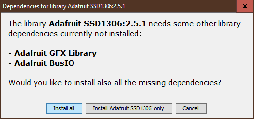
the arduino IDE. Libraries are code that someone else has written that we
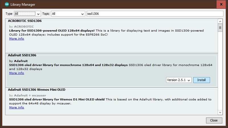
can download and use in our own projects. As an example we will download
the library that makes it possible to use the .96 inch display that comes
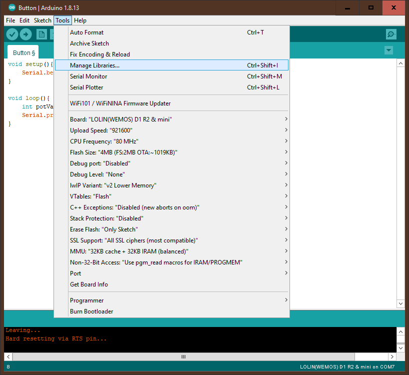
with the Wemos D1 mini starter kit. The first this to do is go to tools
and then click manage libraries
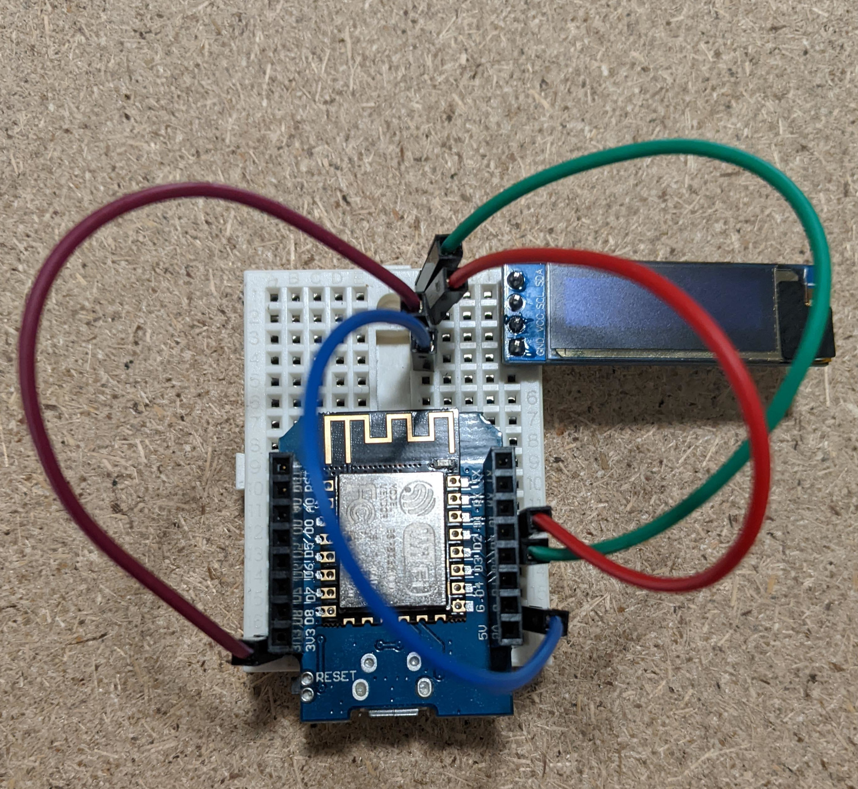
Once the screen is wired up correctly we can load up the example code
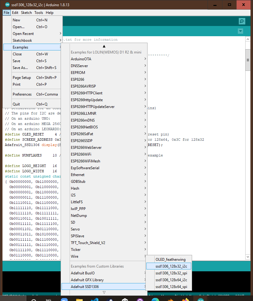
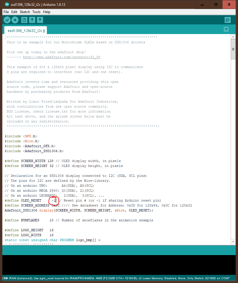
to see it in action. Go to file and then examples and scroll down until you
find Adafruit SSD1306 nd then select the option ssd1306_128x32_i2c
Congratulations!! You have finished the basic arduino tutorial. If you have purchased the Wemos D1 mini Starter kit you can click here to go to the projects page for it.