
This IOT starter kit has everything you need to build all kinds of fun and exciting projects. This guide will walk you step by step through everything from getting your Wemos D1 mini set up to learning the basics of programming a microcontroller to building a bitcoin price tracker or a twitch bot that can listen and respond to your twitch chat and display messages to you in real time! By the end of this guide you will be able to create some incredible things and have the knowledge to start working on your own projects as well!
First things first we should go over what a microcontroller is. At the most basic level a microcontroller is a small computer that can listen for inputs and respond with outputs on its various Input/Output (IO) pins. The Wemos D1 Mini included in the kit is just one example of a microcontroller. By writing code that determineshow the microcontroller responds to inputs the things that are possible are almost endless.
You may have heard of or seen Arduino microcontrollers used in all sorts of projects and wonder what the difference is between those and the Wemos D1 Mini included in this kit. Most of the time the difference between microcontrollers is the number of pins it has and some special features. For our purposes the biggest difference between the Wemos and most other microcontrollers is the WiFi capability the wemos provides. The Wemos is capable of connecting to the internet and this opens the door to a huge range of possibilities. Most of the code we will write is compatible with other microcontrollers and you will be able to take the knowledge gained from this guide and apply it to working with them with no issue.
Before we begin working with the microcontroller we will need software to write and upload our programs to it. We will be using the Arduino IDE(Integrated Development Environment) for all examples in this guide. The Arduino IDE is easy to use and beginner friendly. Click the link below and follow the steps provided on the arduino site to get the IDE installed and ready to use.
If you already have your Wemos set up and ready to go you can skip to
the next section here.
Our Wemos D1 mini is not a regular Arduino board and so we will need
to tell the Arduino IDE how to use it. In order to do this the first
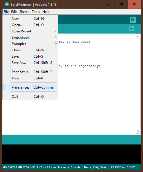
step is to click on File in the top left of the window and then
click on preferences in the menu that drops down.
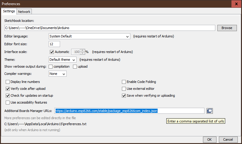
A new window will open and you will see a section for “Additional Boards Manager URLs”. Copy the text below and past it into the box.
Once you have done this press ok to save and close the preferences window and then click on tools at the top of the window. Next in the menu that drops down hover over the selection that says “Board: Something” where the something will be the name of some other microcontroller.
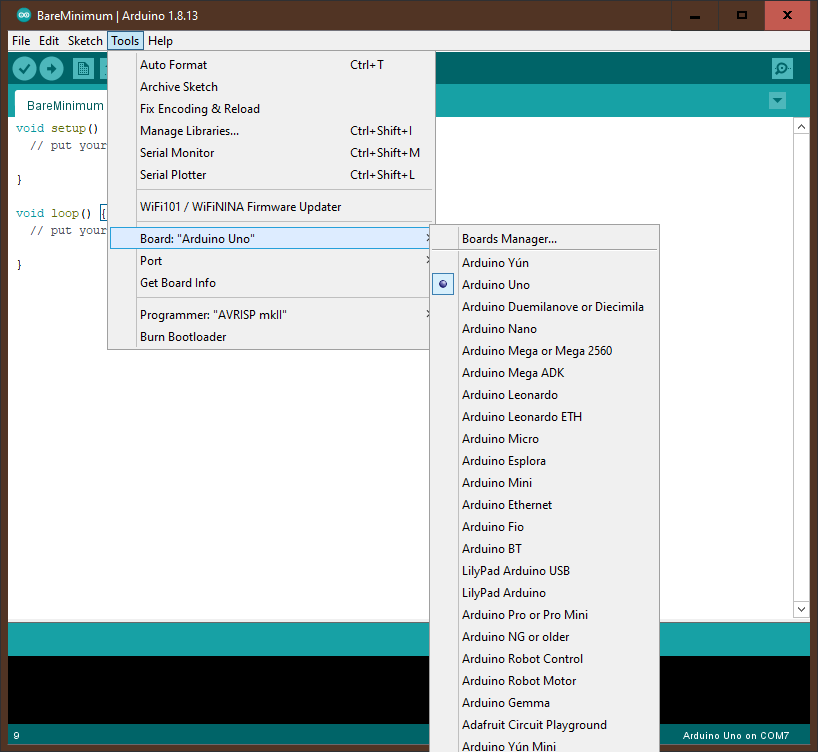
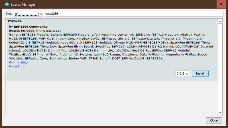
In the next menu that pops up there should be an option for the “Boards Manager” click on this option and a new window should pop up. In this window click on the search bar in the top right and type in esp8266, there should only be one option labeled esp8266. Click install on this option and wait for it to install.
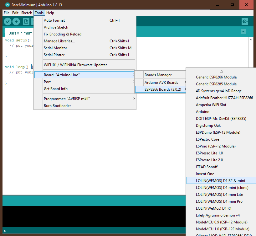
Once it has installed, close the window and restart the Arduino IDE. In order to test that everything is working as it should there are just a few more steps. Go back to the tools/board menu and this hover over the new option esp8266 boards. In the new menu find the option labeled LOLIN(WEMOS) D1 R2 & mini and click on it.
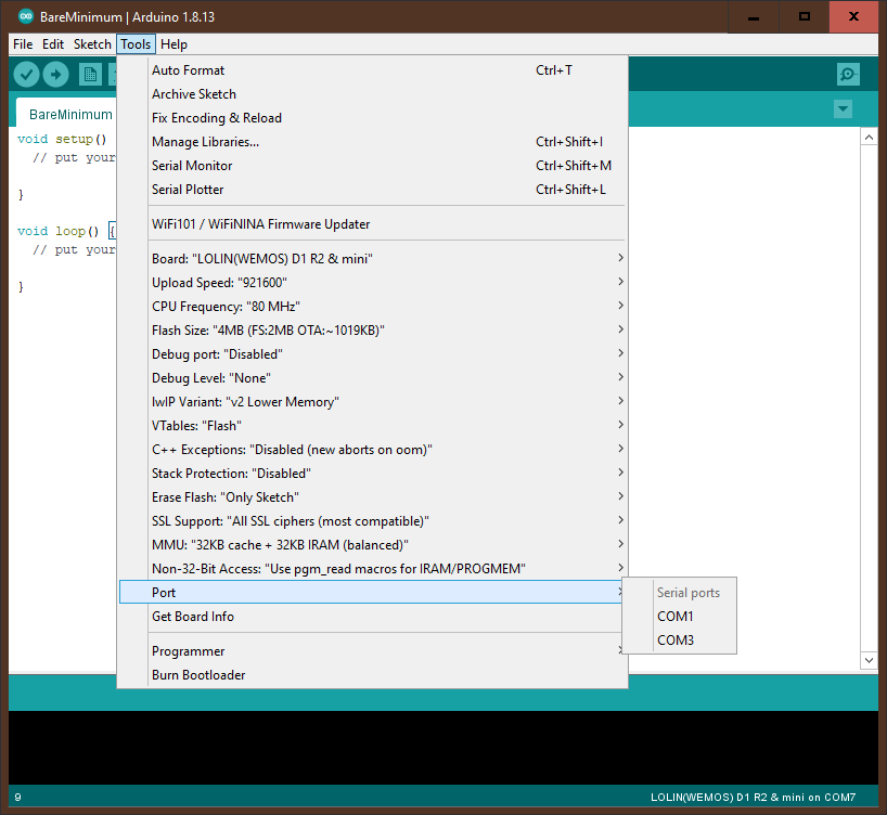
Next make sure that your Wemos is NOT plugged in and in the tools menu find the selection labeled “port” hover over this selection and take note of the currently available ports.
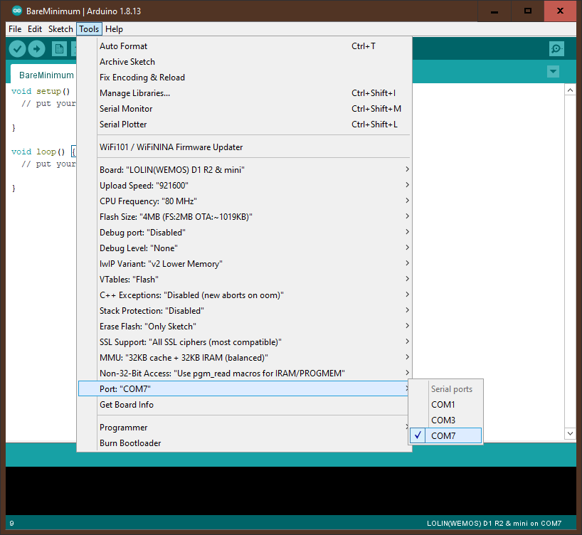
Close the port menu, plug in your Wemos and go back to the port menu. Click on whatever port was added to the list after the Wemos was plugged in.
The final step that will tell us if everything has worked is to go back and click on file in the top left. In the dropdown menu find “examples”. Hover over it and then hover over the option labeled “basic” and then in the new menu click on the option labeled “blink”.
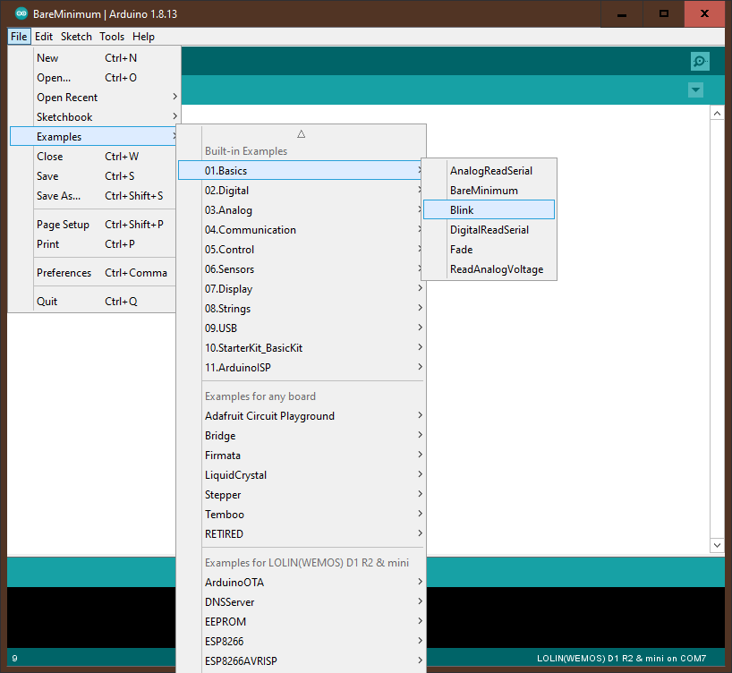
This will open the basic blink sketch that will make the small built in led on the wemos blink on and off. Don't worry about the code for now, we will go over it in the next section. In the top left find the circle with the rightward facing arrow in it and click it. You should see a progress bar in the bottom left corner and then some text should scroll by in the box below it.
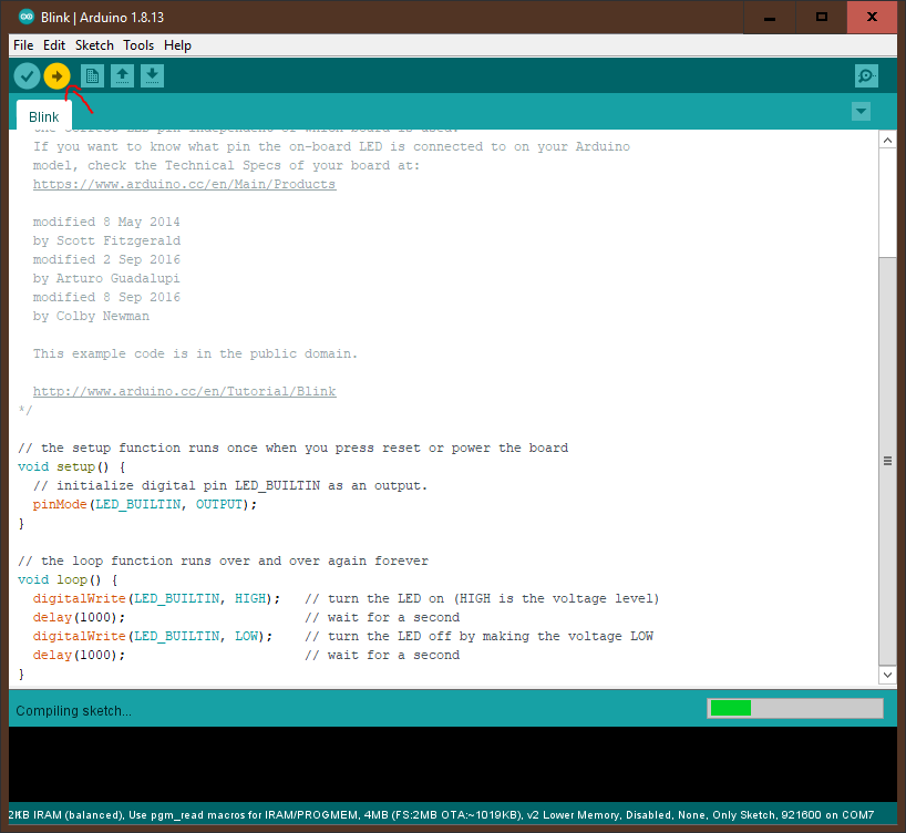
After about 30 seconds to a minute the led on the Wemos should start blinking and everything is working! If everything has worked you can skip to the next section but if you got an error and the bar at the bottom of the screen turned orange we should troubleshoot it now. The left side of the orange bar will have a description of what the error was. One of the most common errors is having the port set wrong. If the error says something like "failed to connect" or "port unavailable" make sure the wemos is plugged in and go back to the port menu to select another one.
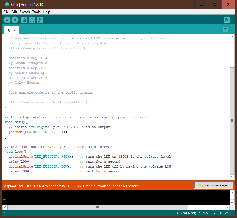
If none of the ports work try unplugging the usb cable from the computer and plugging it into a different usb port. Another error you might see will have something to do with esptool.py. If you see this error you probably need to install python. Instructions for how to do this can be found at https://www.python.org/downloads/. For other more complex errors you can press the copy error message button on the right side of the orange bar and consult the internet for help. There are a huge number of resources online for help with coding and working with microcontrollers and you should be able to find a solution to your problem.
The rest of this page contains some more advanced tutorials that assume you have some previous coding and arduino programming knowledge. If you are brand new to programming check out the programming basics tutorial here. If you already know the basics of programming but are new to Arduino check out the arduino basics tutorial here.
Our first project is going to be intermediate for those who have just
finished the basics tutorial. We are going to set up 3 leds to show
how far our potentiometer has been turned. When the potentiometer is
all the way to one side all 3 LEDs will light up and when it is all
the way to the other none of the LEDs will light up.This project will
require the Wemos, the breadboard, all 3 leds, all 3 resistors, and
the wires.
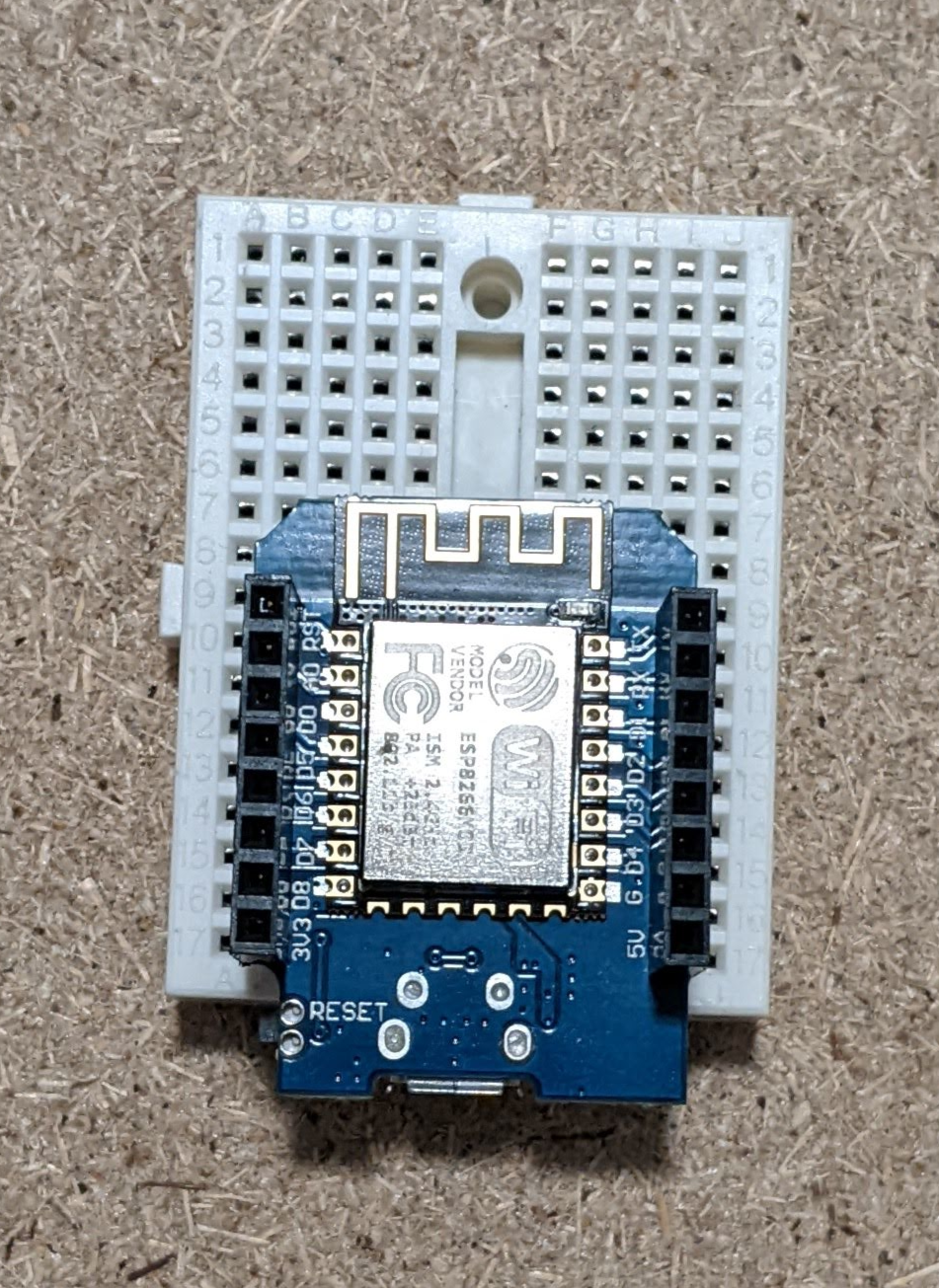
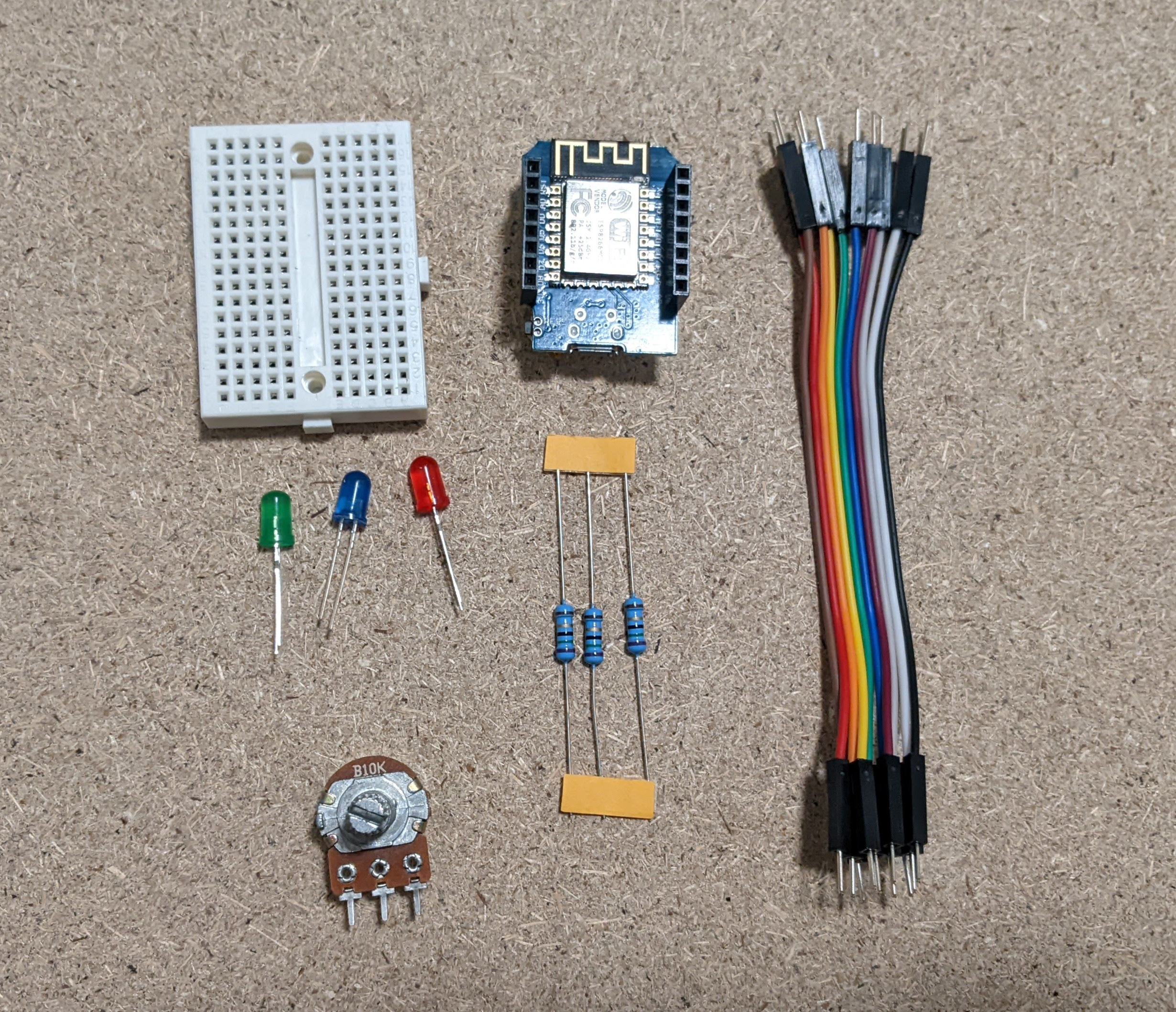 To start we will build the circuit. Start by placing the wemos on
the edge of the board so that there is one column of pins available
on each side and the pins closest to the micro usb port are in the
first row of holes.
 Next we are going to wire up our potentiometer. We want to plug the
potentiometer in so the part that sticks out is off of the board on
the left side. The right pin of the potentiometer if you are looking
at it from the back should be in the top left most hole in the bread
board. we need to connect its right pin to ground, its middle pin to
pin a0 and its left pin to the pin labeled 3v3.
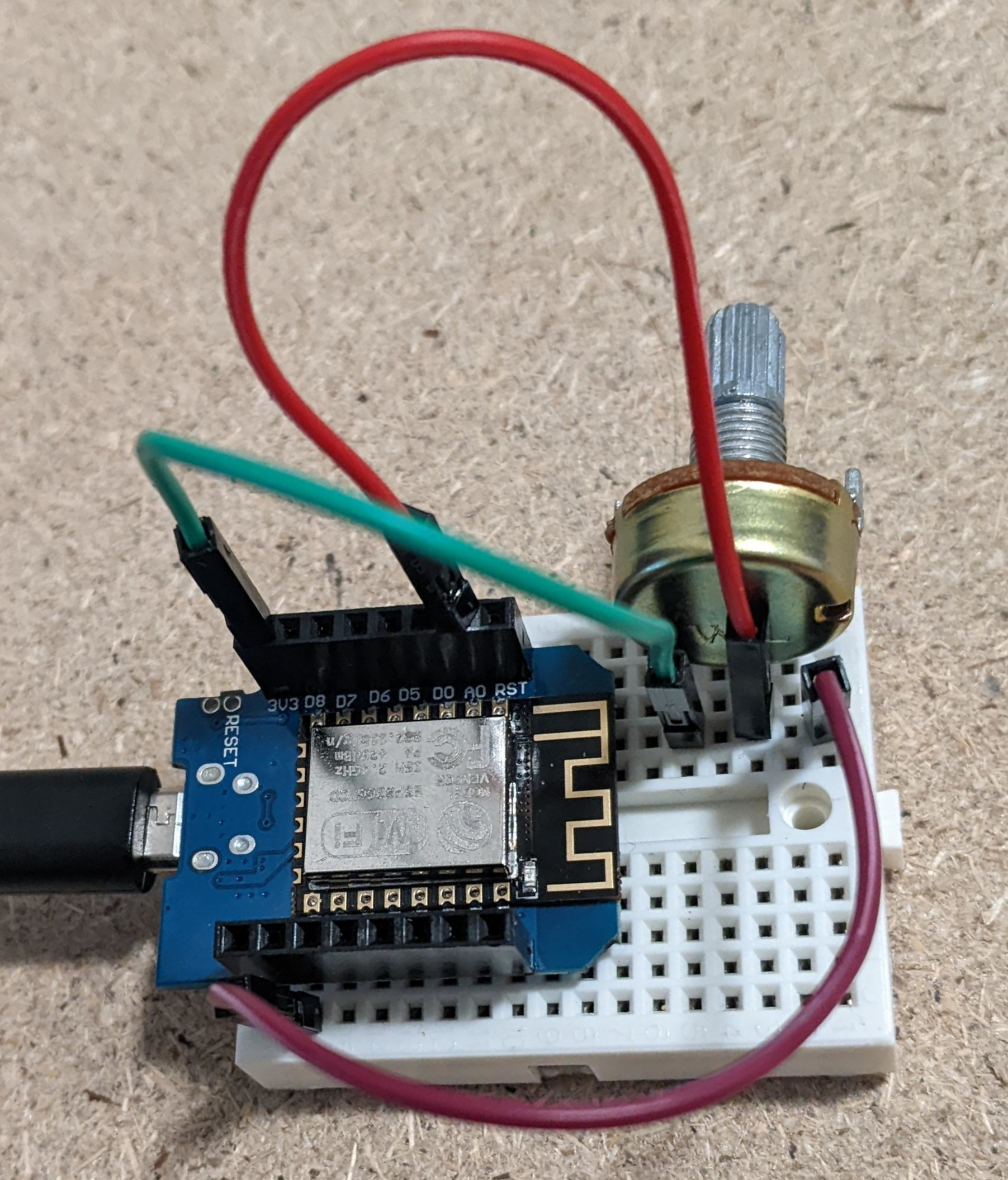 Now that we have the potentiometer set up we need to set up our leds.
We will start by bridging the ground row from the left side to the
right side top rows
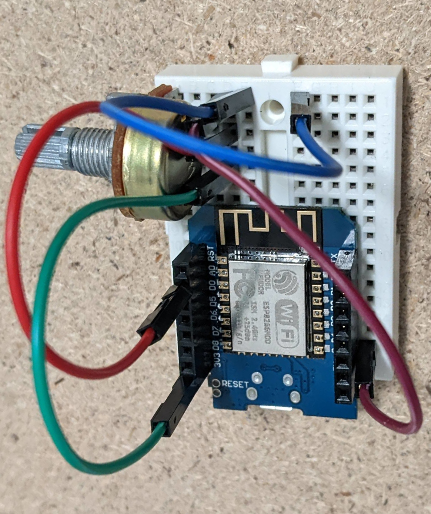 Now we will place our 3 leds in the second column from the right. Make
sure that the ground lef(short) is in the hole one row before the
positive leg(long) for each led
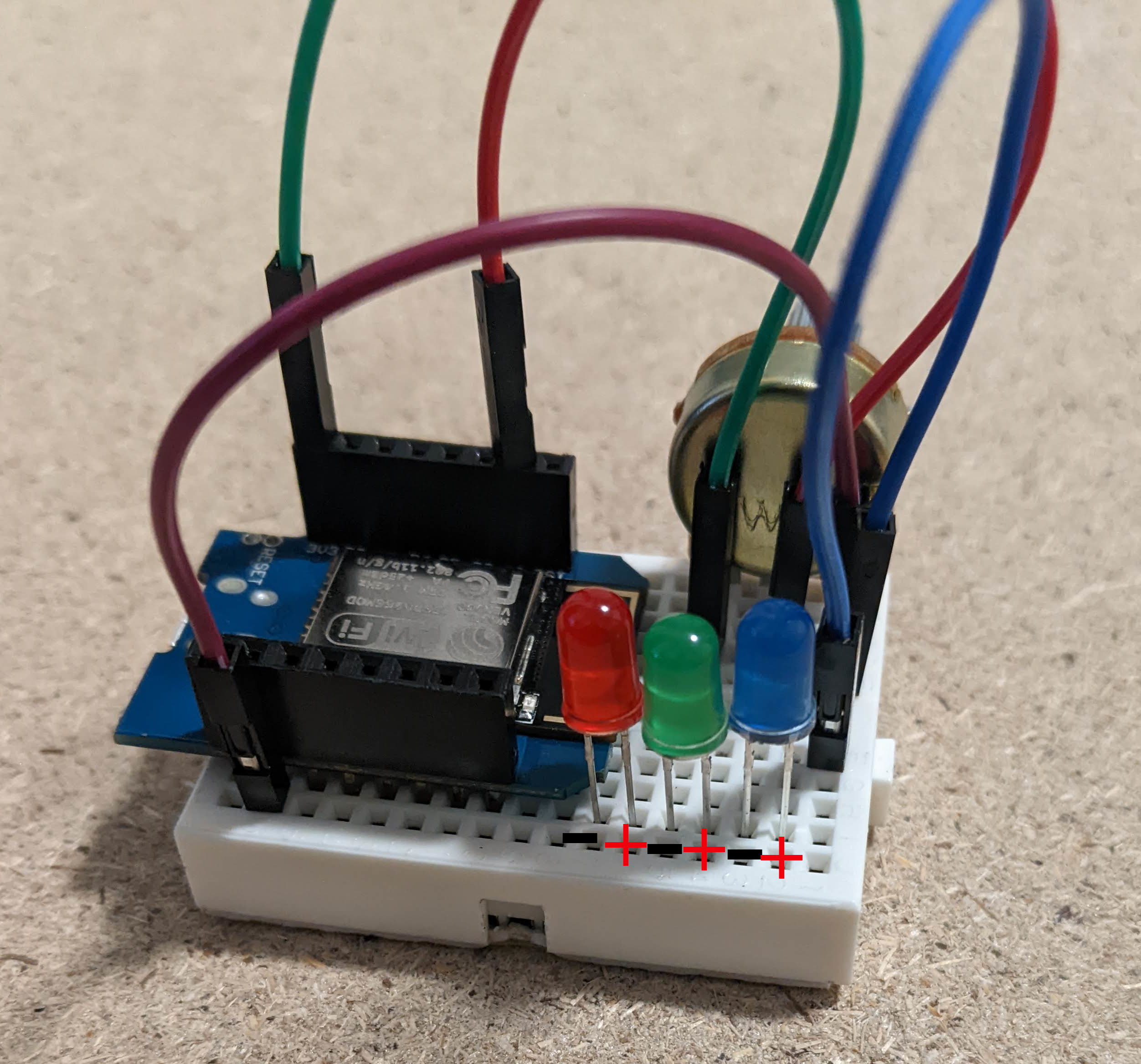 Now we need to connect the ground legs to the ground that we bridged
from the right side. Plug a resistor into the each row that has a
negative LED leg in it and then connect them to the ground at the
top
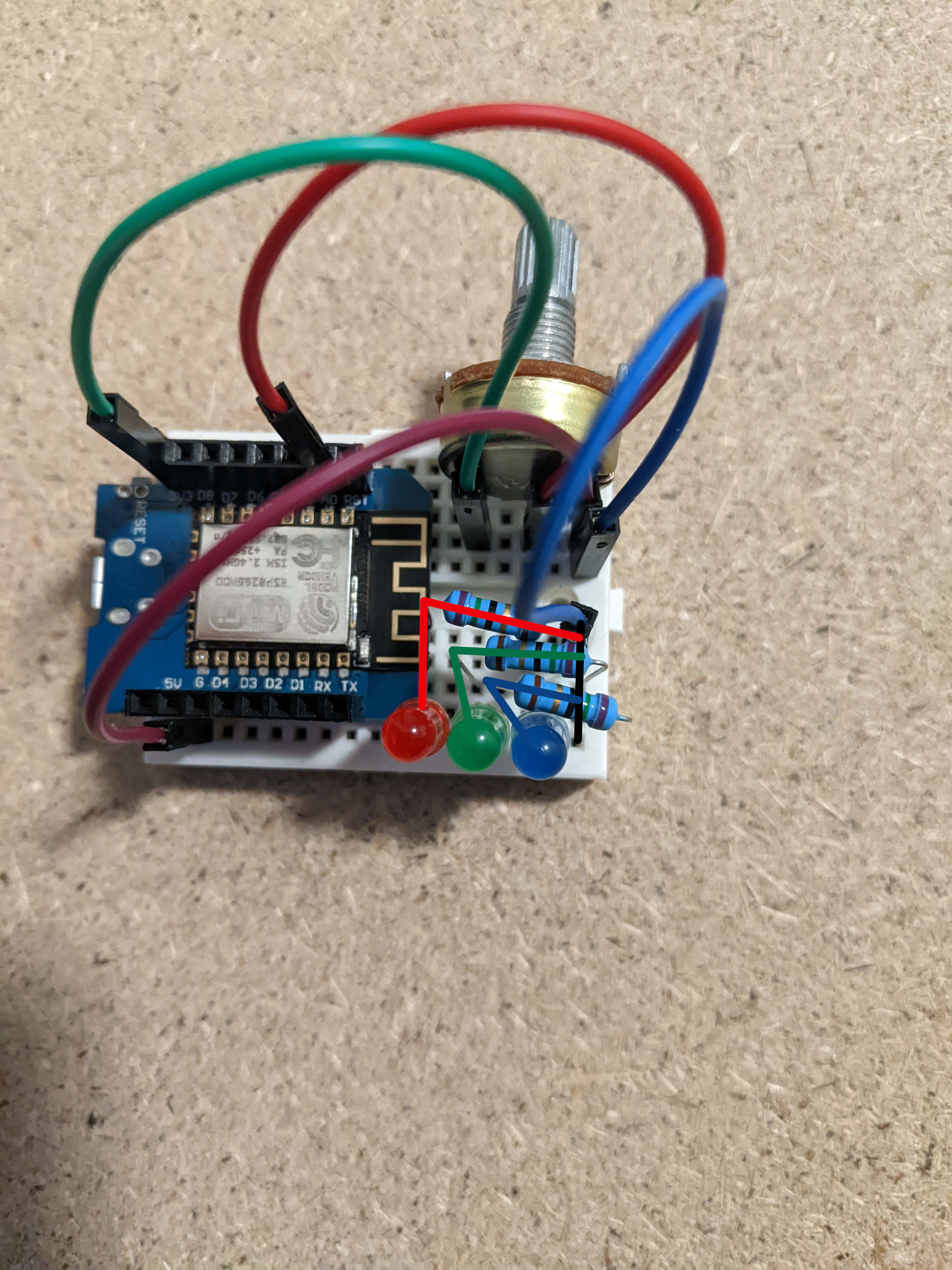 Now we are going to connect a separate pin to each positive leg of
the LEDs. Connect pin D3 to the LED closest to it. Connect pin D2 to
the next closest leg and finally connect D1 to the last LED.
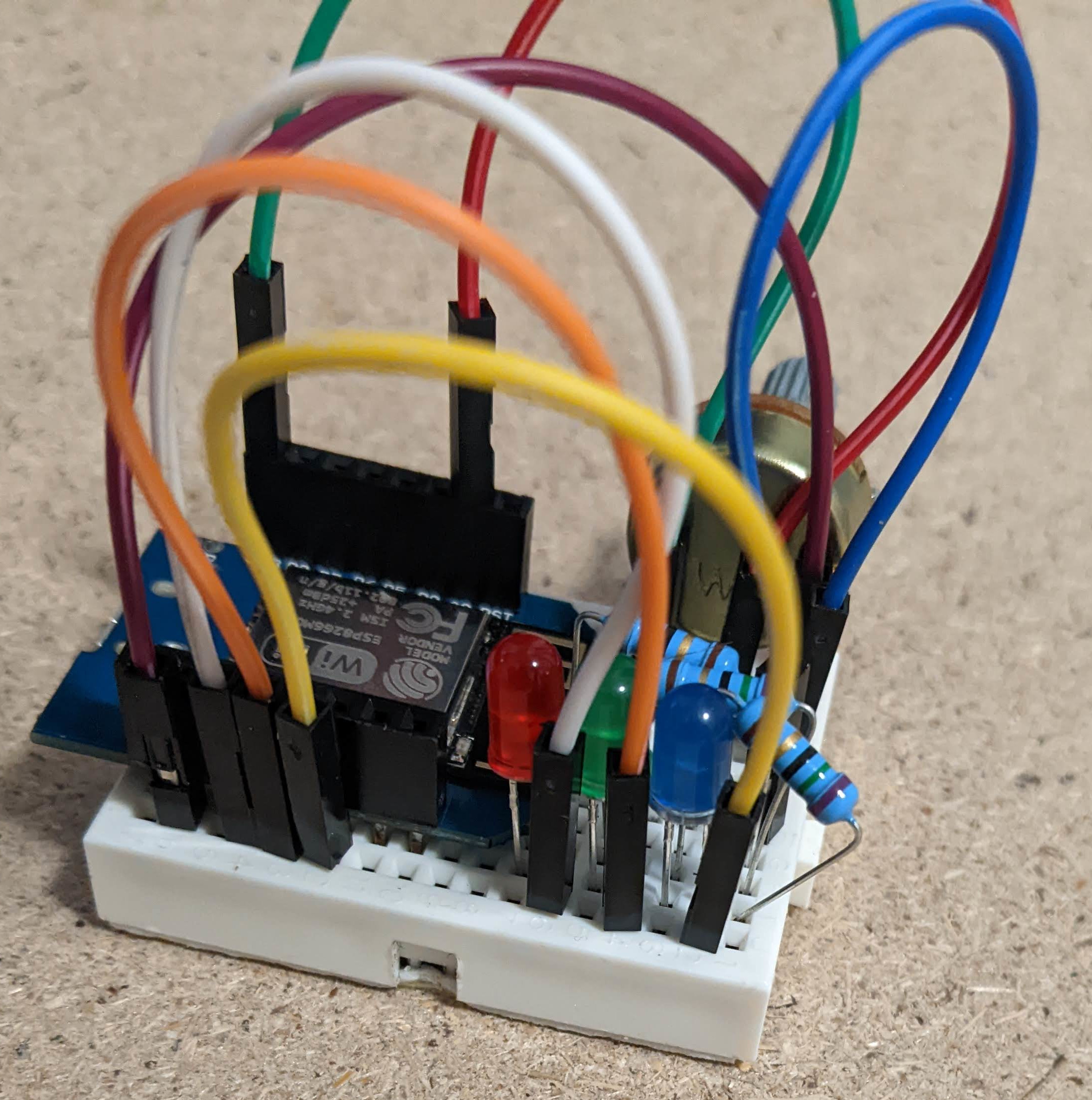 Congratulations you have successfully built the circuit for our first
project. Now we move on to code.
void setup(){
    pinMode(D3,OUTPUT);
    pinMode(D2,OUTPUT);
    pinMode(D1,OUTPUT);
}

void loop(){
    int potVal = analogRead(A0);
    int reducedVal = map(potVal,0,1023,0,3);
    if(reducedVal > 0){
        digitalWrite(D3,HIGH);
    }else{
        digitalWrite(D3,LOW);
    }
    if(reducedVal > 1){
            digitalWrite(D2,HIGH);
    }else{
        digitalWrite(D2,LOW);
    }
    if(reducedVal > 2){
            digitalWrite(D1,HIGH);
    }else{
        digitalWrite(D1,LOW);
    }
}
The only code that is new here that was not explained in the arduino basics tutorial is the map function. The map function takes in 5 parameters, a value to map, the start of the input range, the end of the input range, the start of the output range, and the end of the output range. Effectively what this does is take the 0 to 1024 value we get from analog read and converts it to the range 0 to 3. Press upload and after the program is done uploading you should be able to turn the potentiometer and see the result on the LEDs.
We are going to replace the leds this time with the screen from the kit so that we have a greater resolution. The only thing we need to do is swap out the LEDs we were using for the screen. If you do not know how to setup the screen refer here
#include <Wire.h>
#include <Adafruit_SSD1306.h>

#define SCREEN_WIDTH 128
#define SCREEN_HEIGHT 32

#define OLED_RESET -1
#define SCREEN_ADDRESS 0x3c
Adafruit_SSD1306 display(SCREEN_WIDTH, SCREEN_HEIGHT, &Wire, OLED_RESET);

int lastVal = 0;

void setup(){
    Serial.begin(115200);
    if(!display.begin()){
        Serial.println("Screen setup failed");
        for(;;);
    }
    display.clearDisplay();
    display.display();
}

void loop(){
    int mappedVal = map(analogRead(A0),0,1024,0,128);
    for(int i = 0; i < mappedVal; i++){
        display.drawLine(i,0,i,SCREEN_HEIGHT,SSD1306_WHITE);
    }
    for(int i = lastVal; i >= mappedVal; i--){
        display.drawLine(i,0,i,SCREEN_HEIGHT,SSD1306_BLACK);
    }
    lastVal = mappedVal;
    display.display();
}
This is probably one of the most simple programs we can write to use our screen. The adafruit library provide many functions that let us draw things to the screen, its full documentation can be found here. For our program the only things we are using from the library are the screen setup,clearDisplay(), display(), and the drawLine(). The way that the screen works we can give it as many drawing instructions as we want but nothing shows up on the screen until we call the display function. So essentially what this program does is read our potentiometer value, convert it from 0-1024 to 0-128(the width of our screen)and then draw a number of lines equal to our potentiometer value. The second part takes care of erasing lines as we turn the potentiometer back the other way. At the end of every loop we set a lastVal variable to be equal to whatever the potentiometers current value is. Once we have that value we know that if our new potentiometer value is less than the last value it was we need to erase some lines. To do this, we call the draw line function but instead of drawing in white we draw in black which just means turning off that line. Upload the program and see how the screen reacts to turning the potentiometer.
Now that we have messed around with some basics on the wemos let's get into what makes the wemos special, using the WiFi capabilities. To do this we are going to use some more libraries that make using wifi very easy. These libraries are automatically installed when we set up the wemos so we don't need to worry about that. We are not going to set up any new circuits for this example so let's just dive into some code.Lets start from the top we need to include 3 libraries to make connecting to the internet possible
#include <ESP8266WiFi.h>
#include <ESP8266HTTPClient.h>
#include <WiFiClientSecureBearSSL.h>
The ESP8266WIFI.h gives us functions that allow us to connect to WiFi networks. The ESP8266HTTPClient.h gives us functions that make requests to get content from webpages. The WiFiClientSecureBearSSL.h gives us function that let us make request to secure (https) sites. Next we want to set up the name of the network and the password to connect.
#define STASSID "Your Local Network" //replace with your WiFi name
#define STAPSK  "Your network password" //replace with your WiFi password
We are also going to set up a boolean variable to track whether we should be looping or not
bool looping = true;
We want to loop until we get a respons from the site we are trying to reach so we will set looping to true to start with. Our next steps are going to be to setup our serial monitor to check for responses and connect to the WiFi network
void setup() {
    Serial.begin(115200);

    // We start by connecting to a WiFi network

    Serial.println();
    Serial.println();
    Serial.print("Connecting to ");
    Serial.println(ssid);

    WiFi.mode(WIFI_STA);
    WiFi.begin(ssid, password);

    while (WiFi.status() != WL_CONNECTED) {
        delay(500);
        Serial.print(".");
    }

    Serial.println("");
    Serial.println("WiFi connected");
}
Once we are connected we can start looping and making requests to web pages in our loop function we start by checking if the wifi is still connected and we should be looping
void loop(){
    if (WiFi.status() == WL_CONNECTED && looping) {
Inside of our loop we start by creating an https client
std::unique_ptrclient(new BearSSL::WiFiClientSecure);
client->setInsecure();
HTTPClient https;
setInsecure may seem concerning but we only need to worry about secure connections if we are sending or receiving sensitive information. For now we are just going to be receiving things like jokes which do not have a security concern. Next we are going to make the request in an if statement to get the make it for les homepage. We do this in the if stametn because if the request is unsissessful it will return false and if it is successful it will return true
Serial.print("[HTTPS] begin...\n");
if (https.begin(*client, "https://www.makeitforless.net/")) {
Next we need to actually get the data from the page we connected to which we do below
    Serial.print("[HTTPS] GET...\n");
    // start connection and send HTTP header
    int httpCode = https.GET();
Httpcodes are beyond the scope of this tutorial but they essentially contain some information about the response that we get back.
    // httpCode will be negative on error
    if (httpCode > 0) {
      // HTTP header has been send and Server response header has been handled
      Serial.printf("[HTTPS] GET... code: %d\n", httpCode);
Once we know the connection has been successful and the response from the webpage is good we can read and print out what we got back. When this happens we set loop to false so that we only read from the server one time
      // file found at server
      if (httpCode == HTTP_CODE_OK || httpCode == HTTP_CODE_MOVED_PERMANENTLY) {
        String payload = https.getString();
        Serial.println(payload);
        looping = false;
      }
If we got a negative response code from the webpage we know there is an issue which we can print out
    } else {
          Serial.printf("[HTTPS] GET... failed, error: %s\n", https.errorToString(httpCode).c_str());
    }
Once we are done with the connection we need to close is like so
    https.end();
  } else {
If we couldnt connect to the webpage we print a message
    Serial.printf("[HTTPS] Unable to connect\n");
  }
}
Upload this program and open the serial monitor and you should see the wemos connect and then receive the html code that makes the makeitforless page work. The response we got is not all that interesting but in the next project we are going to contact some other pages called APIs that will allow us to get much more interesting data and print it out on our display
Api stands for application program interface and basically for our purposes they are web pages that return some kind of interesting information. Here is a list of public apis that can do a variety of things. Go ahead and look through this list and see the variety of apis that are out there. For our projects we are going to use apis that do not require authentication. Some pages want you to create and account and get a key so that they can track when you use their api. We don't want to have to worry about that for now. We are going to use the icanhazdadjoke api to request random jokes. Starting with our basic https request code that we wrote in the last project we only need to add 2 lines and change the request webpage to use the joke api. In the loop function when we begin communication we want to specify that we are requesting from the icanhazdadjoke website and after that we need to add two lines
if (https.begin(*client, "https://icanhazdadjoke.com/")) {  // HTTPS
    https.setUserAgent("Wemos D1 mini");
    https.addHeader("Accept","text/plain",true);
These two lines set something called headers that will be sent with our request to the server. The first basically sets a name that identifies our Wemos to the joke server. The second tells the server that what we want back is just plain text. Most of the time these lines are not necessary but looking at https://icanhazdadjoke.com/api we can see that it requests them explicitly. That is all we need to do to request our jokes. Upload the program, open the serial monitor and after the connection is established you should see a joke printed out in the serial monitor. In the next project we will be printing this out to the screen and add a button so that we can request a new joke without having to reset the Wemos
In this project we are going to bring together the screen and our api requests to be able to print our jokes out on the screen. This process is pretty straightforward. The first thing we need to do is import the libraries that let us use the screen.
#include <Wire.h>
#include <Adafruit_SSD1306.h>
We also want to set up definitions for ourscreen width and height as well as set up our screen
#define SCREEN_WIDTH 128 // OLED display width, in pixels
#define SCREEN_HEIGHT 32 // OLED display height, in pixels

#define OLED_RESET     -1 // Reset pin # (or -1 if sharing Arduino reset pin)
#define SCREEN_ADDRESS 0x3C ///< See datasheet for Address; 0x3D for 128x64, 0x3C for 128x32
Adafruit_SSD1306 display(SCREEN_WIDTH, SCREEN_HEIGHT, &Wire, OLED_RESET);
In our setup function after we begin the serial connection we can add
      if(!display.begin(SSD1306_SWITCHCAPVCC, SCREEN_ADDRESS)) {
        Serial.println(F("SSD1306 allocation failed"));
        for(;;); // Don't proceed, loop forever
      }
      display.clearDisplay();

      display.setTextSize(1);      // Normal 1:1 pixel scale
      display.setTextColor(SSD1306_WHITE); // Draw white text
      display.setCursor(0, 0);     // Start at top-left corner
      display.println("connecting to wifi");
      display.display();
This starts the display and print out a message on the screen indicating we are connecting to the wifi. In the loop after we print [HTTPS] GET to the serial monitor we can add
      Serial.print("[HTTPS] GET...\n");
      // start connection and send HTTP header
      display.clearDisplay();
      display.setCursor(0, 0);
      display.println("getting joke");
      display.display();
This will display a message to the screen indicating we are requesting the joke and waiting for a response. Once we receive the response inside of the if statement we add
    if (httpCode == HTTP_CODE_OK || httpCode == HTTP_CODE_MOVED_PERMANENTLY) {
        String payload = https.getString();
        Serial.println(payload);
        display.clearDisplay();
        display.setCursor(0, 0);
        display.println(payload);
        display.display();
This will display the joke we received on the screen. Upload this program and you should see the screen light up and display that it is connecting to the wifi, then that it's waiting for a joke, and then the joke should show up on the screen. The last thing we are going to do is add a button so that we can press it to request another joke. To do this wire up a button that will connect pin D5 to ground. In setup add the line
Pinmode(D5,INPUT_PULLUP);
And at the end of the loop function add
    if(digitalRead(D5)==LOW){
        looping = true;
    }
Then upload this program. The lines we have added make it so that when we press the button and D5 goes low we reset the looping variable that we set to false after receiving our request from the joke server. This triggers another request for a new joke. Try pressing the button and you should see a new joke pop up every time you do.
For our final project we are going to take what we have learned and
use it to make a cryptocurrency proce tracker. It is actually mostly
the same as the joke example but introdiuces one new request concept
and one new screen control concept. We are going to make a request to
the binance api which is able to return a lot of information about
many different crypto currencies. Check out its documentation
here
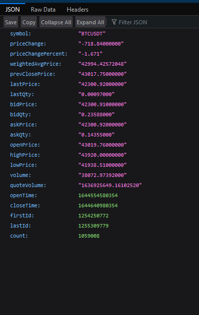
. The binance api is not going to return plain text, instead it will
return a block of json data. Json is a way of representing lots of
data in away that makes it easy to get certain parts. Go to this link
and look at the data that is returned.
google
chrome does not show this in a very nice way but on firefox it looks
like this
#include <ArduinoJson.h>
Once we have imported we can use it. When making our request instead of requesting from the joke server replace the request site with https://api.binance.com/api/v3/ticker/24hr?symbol=BTCUSDT And you can remove the header options we added for the jokes Then inside of the request if statement we need to add a few things
        StaticJsonDocument<500> jsonData;
        deserializeJson(jsonData, payload);
These two lines will turn our json data into a new variable. This is a special variable that we can use like an array except instead of putting a number in the square brackets we can put a string, for example
jsonData["askPrice"]
Replace the payload in Serial.println and display.println with the above
        Serial.println(jsonData["askPrice"]);
        display.clearDisplay();
        display.setCursor(0, 0);
        display.println(jsonData["askPrice"]);
Upload this program and once everything connects you should see that the current price of bitcoin will pop up on the screen. This is the most basic price tracker we can make. In the next section we will upgrade it to display a small bitcoin logo, only show two decimal places on the price and display the percent change.